
Having owned my current Bay Window for about 3 years I finally decided to jump in and do a disc brake and servo conversion. There was nothing wrong with the original drum brakes but having experienced chronic brake fade on more than one occasion it was time to address this issue.
We stock two disc brake kits, the Empi version J42133 and the CSP kit J61833. The Empi kit is supplied complete with master cylinder and reservoir but since I was going down the servo route I decided to go for the CSP kit.
For the servo conversion we stock a range of parts but there isn’t a complete kit as such due to the variations on models, however our sales team can advise on what’s required for anyone wishing to convert any non-servo Bay Window Bus.


Before starting I cracked off the wheel nuts all round and undid the rear hub nuts. Yes, one of them refused to budge even after jumping up and down on a 6-foot bar. A few swift blows from a copper hammer on the side of the nut and it finally let go.
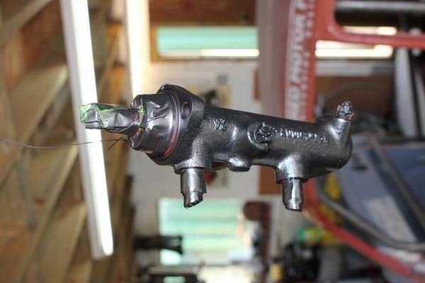
I masked up the master cylinder and gave it a quick coat of primer and then satin black, with hindsight I should have also painted the calliper brackets but didn’t think of this until I was about to fit them by which time it was too late.
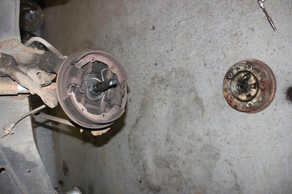
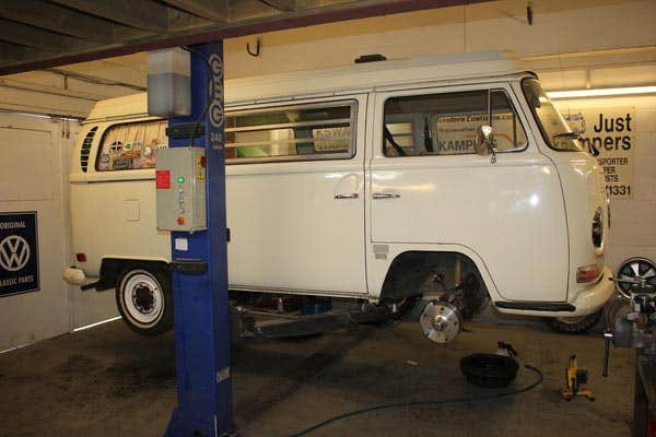
With the Bus on the ramp, wheels removed, and battery disconnected for safety I stripped the drums, brake hoses and complete backplates, with the shoes etc attached. With this out of the way I wire brushed any debris away from the spindle and cleaned off the old grease. I then ran a tap down the 4 threads to make sure they were clean and free of damage.
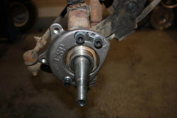
The brackets in the CSP kit have left and right on them so identifying the correct side is easy. The kit comes with all fittings and thread lock. With the thread lock applied to the correct bolts, the brackets were fitted to the spindles.
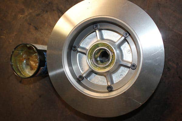

The discs come pre-assembled to the hubs with the outer race installed, so all I had to do was pack the bearing race with grease and pop them in place. The kit is supplied with 2 sets of seals. You need to fit the 50mm seal for Bay Windows, so this was knocked in to place using a seal tool. The disc / hub assembly was installed, and the bearings adjusted. The grease caps were put in place and the speedo cable circlip attached.

Next up I installed the callipers again using the supplied bolts with thread lock. Make sure you have the correct calliper on the correct side with the bleed nipple to the top, then fit the pads with the anti-sequel shims and supplied hardware.

To protect the mounting bolts there are metal cups that need to be fitted. CSP supply in the kit a nylon tool that you use to hammer the caps into place.
The last job was to fit the brake flexis not forgetting to use the small copper washer on the mounting face. I put these in place but didn’t connect the hard lines as these would need to be changed when the servo is fitted.
Start to finish this took less than a couple of hours to fit and I must say I was impressed with the ease of assembly, fit and finish on all the components.


On to the servo. First off, I had to remove the bolts holding the front belly pan and remove this. Undoing the brake pipes from the master cylinder and letting the fluid drain down to the awaiting catch tray (and of course I missed), I then undid the clamp holding the reservoir pipe on, brake switch wiring and undid the 2 M8 bolts for the master cylinder. This was then removed leaving the push rod in place. I pulled the split pin to find the clevis pin was seized into place. Penetrating oil and beating with a hammer failed to move it so this was cut off. Fortunately the servo push rod we supply J41883 comes with a new pin.


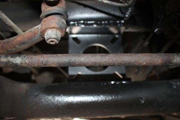
Next up I found the centre line on the axle beam, this is straight forward to do as you have several reference points, The grease nipple in the front of the beam, the centre of the pinch bolt and centre of the idler pin. Using these three points I marked centre. From this point the nearest edge of the servo bracket needs to be 135 mm from centre. This was measured and scribed. Now knowing where the servo bracket would sit I degreased the relevant area and removed the paint from the upper and lower axle tubes, and put the bracket in place. This is an interference fit and will need tapping into place.
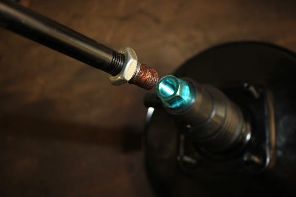
We stock a couple of servos for the Bay Window J10509 for the 1974 to 79 model and J40128 for the 1971 to 74 model. I decided to use the later unit as its slightly slimmer, so offered more clearance. With the servo rod installed using anti seize on the threads I then installed the servo on the bracket, so I could check alignment and clearance. The bracket needs to be as far back on the beam as possible, but you do need to check movement on the steering idler. Cycle the steering from lock to lock ensuring there is a gap between the ball joint and bracket. Once I was happy I tacked the bracket in place.
With the servo removed I then fully welded the bracket to the upper and lower axle tubes, once cooled this was primed and painted.

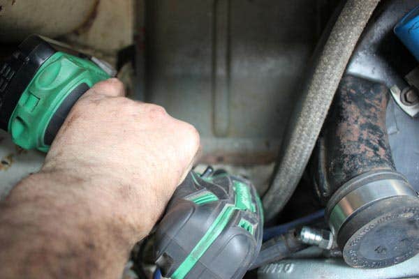
For the servo you need a vacuum supply from the engine, if you’re lucky your inlet manifold will already have a take-off point, mine didn’t. We offer a couple of options on this, a Twin port manifold with a threaded insert for a take-off J12750 or for a single port we currently stock a manifold with a take-off J14570 (but please check if your are ordering one of these). Although my van is an Early Bay it’s been fitted with a twin port engine, so this allowed me to tap into the Left-Hand cast manifold and I was able to do this without removing the engine. This was done by removing the pre heat pipes from the exhaust, undoing the manifold boots, the centre bolt on the manifold and undoing the alternator clamp then loosening off the side bolt on the fan housing. With the two bolts removed from the manifold I was able to slightly lift the fan housing / alternator allowing the manifold to come up and the inlet manifold to be jiggled away from its mounting studs.


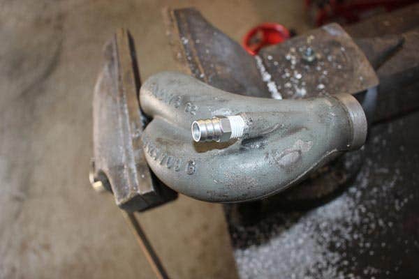
With the manifold removed you can see the raised lug for the vacuum take off. Not all of these had this. If you’re doing this conversion and don’t have the lug we stock a replacement J20383. With the manifold clamped in a vice I centred the lug and drilled a pilot hole then worked up in bit size to the correct tapping size. I then tapped this to a BSP tapper thread and fitted a threaded insert with PTFE tape. I then reinstalled the manifold with a new gasket.
I need a route for the servo pipe from the engine bay, so on the left-hand side next to the wiring loom, I checked the rear side to make sure nothing was in the way then drilled a hole and opened this up with a step drill to allow clearance for the servo hose. I de-burred then painted the bare edge fitted a grommet and put the hose in place.

The system requires a non-return valve to stop the servo stalling the engine, so I used a short length of servo hose J18127 to our valve J11061. This must be fitted the correct way around and has an arrow showing the flow, this need to point towards the engine. On our unit the engine end is black so easy to distinguish.

I needed a line from the engine to the servo. This could be done simply with servo hose, but I wasn’t happy with how this would mount or look, so a 2-metre length of 12mm OD aluminium tube was purchased from eBay. I was in luck with this as on my Bus there was a series of 12mm holes in the top hat sections that the tube passed through. It took a bit of messing about to feed it in, then a slight curve in the rear allowed it to pass over the rear torsion tube and connect to the servo hose from the engine. Another short length of hose connected the tube to the servo. This may not be possible on other year / variants of Bus, so an alternative method may be required.


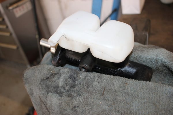
With this conversion you will need the appropriate servo master cylinder. This has a built in residual valve for disc brakes, our part J10257. With the master cylinder held in the vice with a cloth to protect it, I installed the reservoir grommets J13823 using brake fluid as a lubricant to help fitting. With these in again, using brake fluid I pushed home the reservoir J41029. I put the outlet pointing to the rear but once on the van I decided to turn this around for clearance reasons. A new brake light switch J10534 was also fitted.
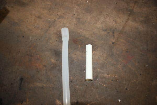
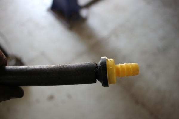
A lot of the brake conversions available use a fill reservoir on top of the master cylinder J17013 but I wanted to keep the top up bottle under the dash for ease of use. I used our reservoir pipe J40765 and then found a length of pipe in our scrap bin that fitted the inside diameter. I then used this to sleeve between the new pipe and the old pipe to extended it to the inlet. Using a hot air gun, I gently heated the new pipe allowing a gentle curve, so it flowed smoothly.

The old brake pipes were all in the wrong place, so new ones were installed. The two front pipes need to go to the front of the master cylinder and the rear pipe nearest the servo. We stock various pipe lengths and again this may vary depending on models / years. The pipes were now connected to the front flexi pipes and the flexi hose clips reinstalled along with new grommets (J10967) where the pipes pass through the chassis.


That was the conversion complete, but I also wanted to check the rear brakes. With the drums removed I found one-wheel cylinder was weeping so I decided to replace both sides. One of the adjusters had also seized so I replaced these, reinstalling with anti-seize so hopefully this won’t happen again. Looking at the rear brake pipes they looked OK but when undoing one-wheel cylinder the pipe fractured so both sides were replaced with J40668 pipes. The shoes were in good condition, so these were sanded along with the drums to remove the glaze and then reinstalled. Drums back on the rear brakes were adjusted. I then filled the top reservoir with brake fluid (J10646) checked for leaks, then pressure bled the system. With the brakes bled I then pumped the pedal a couple of times to square the rear shoes and re-adjusted them.


The front wheels went back on. The conversion kit uses studs, so you will need to replace your old wheel bolts with nuts J10569, again these were installed with anti-seize.
With the van off the ramp I went for my first test drive. This conversion has transformed the van. The brake pedal used to be hard and slow to respond. Now the brakes are light and you can feel the van slowing as soon as you touch the pedal. I drove a few miles home and then jacked the van up, checked and reset the front wheel bearings and looked over all the lines to make certain there were no leaks. I'll drive the van a few hundred miles then re-check, adjust the rear shoes and bearings for peace of mind.
PRODUCTS MENTIONED IN THIS ARTICLE:
>